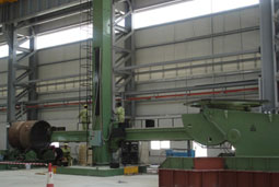
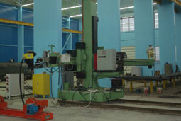
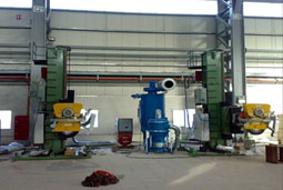
Column and Boom Manipulator
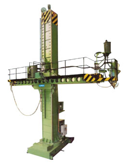
12MX12M COLUMN & BOOM
MAJOR POINTS :
- The Columns of both the RC and TRC types are supported on precision crossroll bearings. The larger machines have pre-loaded cross-roll bearings, which eliminates the free play, and which is extremely important since any play in the cross-roll bearing is considerably increased at the end of the boom when it is in the fully raised and fully extended position.
- Column rotation can be motorized, but in any case all “AMIN” machines have a manual locking arrangement to lock the column in any of the 360° Positions.
- The boom saddle, or carriage, is fitted with rollers which travel along the machine slide-ways. Each of the rollers is fitted with pre-loaded Taper Roller bearings carried on eccentric shafts. The Rollers can be adjusted for wear and tear and also for precision and vibration-less travel.
- Boom elevation is through high torque AC Geared Motor incorporating an electromagnetic brake, the final drive being through rack and pinion. Some of our competitors still employ chain elevation which we consider unsatisfactory since it is impossible to eliminate “bounce”. Bounce accumulates particularly where a Welder’s platform or Lay Trough is fitted and is aggravated by any movement of the welder. Some of our competitors use lead-screw elevation which is unsatisfactory since flux, dust etc. accumulate and the lead-screw then becomes locked in the lead-screw nut. Both chain and lead-screw method are used by this company and discarded some years ago.
- A further important point is that the actual boom elevation and boom traverse drive is mounted on the saddle itself.
- “AMIN” ensure that the boom/saddle/welding head, etc. are fully counterbalanced by a weight which moves up and down inside the column, which takes considerable strain away from the elevation gearing. The counter balance weight is connected to the saddle by a heavy duty wire rope/ Leaf Chain which incorporates an anti-fall device.
- The boom traverse drive is achieved through AC Frequency Variable Drive & AC Motor, reduction gearing and final rack and pinion drive.
- A most important feature of the “AMIN” machine is the design of the machine slide-ways along-with the very wide rollers, which are carried in the saddle, traverse.
- Speeds :
We understand that the Rotators and Column & Boom Manipulators may be used for cladding operations and we should mention that in these cases very slow movements are essential. We can incorporate in the “AMIN” traverse drive 2 speed gear box which enables the boom to be retracted very slowly, e.g. – - The speeds could be 5 mm - 100 mm
Second gear 50 mm - 1000 mm - With these speeds it is possible to arrange for the boom to be retracted at very slow speed when spiral cladding, using either the strip method or the wire electrode method.
- Deflection :
We have mentioned above that one way of overcoming this matter is by using a precision cross-roll bearing on which the column rotates. The design of the slide-ways and the very wide service area on which the supporting rollers traverse also helps. However, we have had very considerable experience in Column and Boom design and developed a method of fabrication which enables us to offer Columns and Booms with a much better deflection figure than any of our competitors. We do in fact build in five different designs in order to ensure that the Column and Boom is correct with controlled deflection relative to height, boom travel and weight to be carried.
COLUMN & BOOM MANIPULATOR MODELS :
| Machine classifications: | |||
| 1/RMB | - | 1/TRMB | Portable |
| 2/RMB | - | 2/TRMB | Middle weight |
| 3/RMB | - | 3/TRMB | Medium Duty |
| RC | - | TRC | Universal Type Heavy Duty |
| 1/RC | - | 1/TRC | Extra Heavy Duty |
“AMIN” Column & Boom Manipulators are built in five different designs.
These groups cover a range of machines comprising 1/RMB upto Heavy Duty machine 1RC – 12 M x 12 M. The latter machine having 12 Mtr. Maximum height under Boom and 12 Mtr. arc travel.
The recommendation as to the most suitable Manipulator to meet requirements depends upon.
1. Length of Boom and maximum height under Boom
2. Weight carried at the end of the Boom – welding head – operator’s seat or lay trough – welder’s platform and additional welder’s walkway running total length of the Boom.
Thus, a Column and Boom can have smaller dimensional proportions and yet be of more robust design than a Column and Boom which has a greater horizontal and vertical Boom travel.
It will be understood from the classifications that in developing the different groups of machines we have had to take into consideration the very exacting requirements of some of our customers, in particular those engaged in cylindrical vessels manufacture where we have to meet a specification for a Manipulator to carry approximately 300 Kgs. carried at the end of the Boom and maintain a deflection of better than 8 mm.
The Manipulator comprises four essential components.
FREE STANDING BASE (OR TRAVELLING CARRIAGE)
COLUMN – SADDLE – BOOM
Much theory has been written on the design of these four main components, but the fact remains that ultimately the machine has to be built and carry out the correct functions required by the customer for his exact requirements.
The following points will be of interest.
FREE STANDING BASE OR TRAVELLING CARRIAGE :
We have developed an extremely robust fabricated design which has a minimum depth to give the necessary rigidity. If the depth of the Base is sacrificed in order to give a slightly lower minimum height under Boom, then some rigidity must be sacrificed. The base top plate is of extremely generous dimension, which varies according to the size of the machine.
The Base design is such that the machine is free standing when the Boom is being operated in the maximum height and fully extended.
The Base can be either stationary or can be supported on four single flanged wheels to form a Traveling Carriage. Alternatively, two double flanged wheels and two plain wheels to travel along the track-way. In this case the Base incorporate either constant speed or variable speed drive. By utilizing two double flanged and two plain wheels, accurate tracking can be ensured where it is required to weld with the Column traversing.
The Column is supported on a cross-roll bearing (not a plain ball bearing, as used by some competitors). The larger machines are fitted with pre-loaded cross-roll bearings, which eliminate the “free-play” at this point, thus reducing Boom deflection. If a ball bearing is used, deflection must arise because all ball bearings must have a clearance. The diameter of the cross roll bearing ranges from 430 mm to 1660 mm
Clamps are provided so that when the welding head is in the correct position the Column can be manually securely located.
Motorized Column rotation can be incorporated. In this case the cross roll bearing has an integral spur gear on the periphery. In the case of RC/TRC Universal manipulators rotation is achieved an AC motor and one reduction gear box but on the later machines, rotation is achieved through an AC motor and two heavy duty reduction gear boxes, which engage directly with the integral spur gear, thus eliminating backlash.
The Column rotation of the large Manipulators with very long Booms incorporates a special drive to smoothen out starting and stopping of rotation, thus reducing the strain, which would otherwise be placed on the reduction drive.
Send EnquiryAmin Products Range
Our Clients


